Chapter 4
Operational Amplifiers
m4.2 Noninverting Amplifier
The circuit in Figure m4.2 uses a potentiometer whose total resistance is R1. The
movable stylus on terminal 2 creates two variable resistors: βR1 between
terminals 1–2 and (1 - β)R1 between terminals 2 and 3. The movable stylus
varies β over the range 0 ≤ β ≤ 1.
- Obtain an expression for G = vo/vs in terms of β.
- Calculate the amplifier gain for β = 0.0, β = 0.5, and β = 1.0 with
component values R1 = 10 kΩ and R2 = 1.5 kΩ.
- Let vs be a 100-Hz sinusoidal signal with a 1-V peak value. Plot vo
and vs to scale for β = 0.0, β = 0.5, and β = 1.0.
NI Multisim Measurements
- Enter the circuit of Figure m4.2 into NI Multisim. Use these specific
components: OPAMP_3T_VIRTUAL, AC_VOLTAGE, and virtual linear
potentiometer; see the video tutorial below to learn how to search for
parts by name. Set the AC voltage source frequency to 100 Hz.
- Observe vs and vo with the oscilloscope. Vary the potentiometer value
over its full range of 0 to 100%, and then use the oscilloscope cursors
to measure the circuit gain for β = 0.0, β = 0.5, and β = 1.0.
- Print screen shots of the oscilloscope for β = 0.0, β = 0.5, and
β = 1.0. Use the same Channel A and Channel B vertical scale (volts
per division) for all three screen shots.
Additional helpful tips:
- Use the Simulate → Instruments → Oscilloscope with vs on
Channel A and vo on Channel B. Run an interactive simulation until
several cycles of oscillation appear on the oscilloscope display.
- Use the cursors to measure the peak values of the input and output
signals, and then calculate the amplifier gain as the output value
divided by the input value.
NI Multisim video tutorials:
NI myDAQ Measurements
- Build the circuit of Figure m4.2 with the given component values. Use the
following myDAQ signal connections:
- AO0 (Analog Output 0) for vs,
- AI0 (Analog Input 0) to display vs; connect AI0+ to the source
voltage and AI0- to ground, and
- AI1 (Analog Input 1) to display vo; connect AI1+ to the output
voltage and AI1- to ground.
Create the 100-Hz sinusoidal waveform with the NI ELVISmx Function
Generator.
- Observe vs and vo with the NI ELVISmx Oscilloscope. Vary the
potentiometer value over its full range of 0 to 100%, and then use the
oscilloscope cursors to measure the circuit gain for β = 0.0, β = 0.5, and
β = 1.0.
- Print screen shots of the oscilloscope for β = 0.0, β = 0.5, and β = 1.0. Use
the same Channel 0 and Channel 1 vertical scale (volts per division) for all
three screen shots.
Additional helpful tips:
- Use the Texas Instruments TL072 op amp
described in Appendix C.
Follow the pinout diagram of Figure
C.1 for either of the two
available op amps in the package. You may also use an equivalent
dual-supply op amp.
- Power the op amp with myDAQ +15V to V CC+ and -15V to V CC-.
Use AGND for the circuit ground.
- The potentiometer terminals of Figure m4.2
follow the standard pinout used by single-turn trim potentiometers.
If your potentiometer does not label the pins, the stylus pin (Pin 2) is
normally placed between Pins 1 and 3.
NI myDAQ video tutorials:
Further Exploration with NI myDAQ
Signal amplifiers apply a gain G ≥ 1 to increase the amplitude of weak signals,
thereby making the signal information easier to use elsewhere in the system. Use
a voltage divider circuit (known as an attenuator in this context) to create a
“weak” signal from a portable audio player or computer audio output and then
investigate how well the amplifier you built in this problem can restore the
original signal strength.
- Add the two-resistor voltage divider circuit to your amplifier as
shown in Figure m4.2a.
- Connect one plug of the 3.2 mm stereo cable supplied with your
myDAQ kit to your audio player. Connect the other plug to the
attenuator input vm as shown in Figure m4.2a to apply the left
channel of the stereo audio signal to the attenuator input.
- Play some music and observe the signal vs with the oscilloscope.
Confirm that signal is indeed “weak” – its amplitude should be well
under one volt peak.
- Observe the amplifier output signal vo with the oscilloscope. Confirm
that you can adjust the circuit gain to strengthen the music signal’s
amplitude.
- Connect your earphones to the circuit output and listen as you vary
the circuit gain.
IMPORTANT – PROTECT YOUR HEARING!
Do NOT disturb your circuit connections while you are wearing
earphones. Accidently shorting together circuit connections can
produce a very loud and unexpected noise. Alternatively, use a
speaker to listen to the amplifier output or hold the earphones some
distance from your ears.
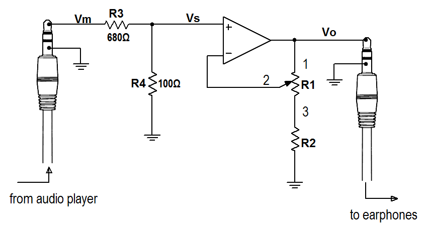
Figure m4.2a: Circuit for Problem m4.2 with voltage-divider attenuator
and audio signal connections. The music signal is vm, the attenuated
signal to be amplified is vs, and the amplified signal is vo.