Chapter 3
Analysis Techniques
m3.4 Thévenin Equivalents and Maximum Power Transfer
In the circuit of Fig. m3.4, find the Thévenin equivalent of the circuit at
terminals (a,b) as seen by a load resistor RL. Specifically:
- Determine the open-circuit voltage V OC that appears at terminals
(a,b).
- Determine the short-circuit current ISC that flows through a wire
connecting terminals (a,b) together.
- Determine the Thévenin resistance.
- Determine the maximum power PLmax that could be delivered by this
circuit.
Use these component values: V SRC = 10 V, R1 = 680 Ω, R2 = 3.3 kΩ, R3 = 4.7 kΩ,
and R4 = 1.0 kΩ.
NI Multisim Measurements
- Enter the circuit of Figure m3.4 into NI Multisim. Connect a resistor
RL as a load between terminals (a,b).
- Use interactive analysis and measurement probes to determine the
open-circuit voltage.
- Use interactive analysis and measurement probes to determine the
short-circuit current.
- Run a parameter sweep to plot the load resistance power as a function
of load resistance connected between terminals (a,b). Use a plot
cursor to determine the value of maximum power.
These tips provide more detail about the Multisim techniques for this problem:
- Place a measurement probe on terminal b to display the load current.
- Place a measurement probe on terminal a referenced to the probe you
placed on terminal b to display the voltage across the load.
- Set the load resistance to a small yet finite value such as 0.1 Ω. Run
the interactive simulator to determine the short-circuit current.
- Set the load resistance to a large yet finite value such as 100 MΩ; enter
this value as 100MEG rather than 100M because ”m” means ”milli”
regardless of case. Run the simulator to determine the open-circuit
voltage.
- Set up a Simulate → Analyses → Parameter Sweep to plot P(RL)
over the range 1 Ω to 10 kΩ. Choose a linear plot type, select
“DC Operating Point” for “Analysis to Sweep,” and plot 100
evenly-spaced points to create a smooth curve.
- Use the plot cursors to find the maximum value of the load
power. Compare this value to the maximum power you calculated
analytically.
NI Multisim video tutorials:
NI myDAQ Measurements
- Build the circuit of Figure m3.4. Calculate the Thévenin equivalent
circuit from the measurements taken in the next two parts.
- Recall that the DMM voltmeter has very high resistance and thus
appears as an open circuit. Connect the voltmeter between terminals
(a,b) to measure the open-circuit voltage.
- Also recall that the DMM ammeter has very low resistance and thus
appears as a short circuit. Connect the ammeter between terminals
(a,b) to measure the short-circuit current.
- Connect the variable load circuit shown in Figure 3.4a between
terminals (a,b) and connect the myDAQ analog input channels to
measure the overall load voltage and the voltage that appears across
the shunt resistor; this latter voltage is proportional to the load
current. Run the LabVIEW VI “VIPR.vi” (described below) to display
the load’s voltage, current, power, and resistance. First sweep the
potentiometer throughout its full range to get a sense of the overall
behavior, and then collect and tabulate at least 10 measurements
of load power and load resistance; adjust the potentiometer to take
measurements in 1 mW steps. Also record the maximum power and
associated load resistance. Finally, plot the load power as a function
of load resistance.
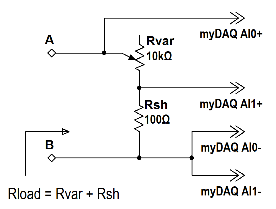
Figure m3.4a: Variable load with potentiometer (variable resistor) Rvar
and shunt resistor Rsh. The total load resistance is Rvar+Rsh. NI myDAQ
Analog Input 0 (AI0) monitors the overall load voltage between terminals
A-B and Analog Input 1 (AI1) monitors the voltage across the shunt
resistor; the load current is the shunt resistor voltage divided by Rsh.
LabVIEW “VIPR.vi” details:
- The LabVIEW VI “VIPR.vi” measures the overall load voltage on
analog input channel 0 (AI0+ and AI0-) and the shunt resistor voltage
on analog input channel 1 (AI1+ and AI1-). Enter the measured shunt
resistance for best accuracy. “VIPR.vi” calculates the load current as
the voltage on AI1 divided by the entered shunt resistance value, the
load power as the product of load voltage and current, and the load
resistance as the load voltage divided by the current.
- The measured current value can become somewhat noisy, and
“VIPR.vi” applies a noise filter to improve your ability to read the
display. The noise filter calculates the average value of all of the
measurements accumulated since the last time the measured voltage
changed by at least 0.01 volts. Disable the noise filter, if desired.
- “VIPR.vi” is linked at the bottom of
http://decibel.ni.com/content/docs/DOC-16389.
Download this source file and double-click it to open in LabVIEW;
click the “Run” button to start the VI.
NI myDAQ video tutorials:
Further Exploration with NI myDAQ
Try this simple yet effective technique to directly measure Thévenin
resistance:
- Measure the open-circuit voltage at terminals (a,b),
- Connect a variable resistor as the load (10 kΩ potentiometer works
well for this circuit),
- Monitor the load voltage and adjust the potentiometer until the
voltage is exactly one half of the open-circuit voltage,
- Disconnect the potentiometer from the circuit, and
- Measure the potentiometer resistance with an ohmmeter; this value
is the Thévenin resistance.
Apply this method to the circuit of this problem and compare your results to
your other measurements of Thévenin resistance.
Explain why this method works. Hint: Consider a Thévenin equivalent
circuit connected to a load resistor and recall what you know about voltage
dividers.